Item In Stock
A drop-in, flange-mounted, cartridge-style, pilot-operated, spool-type reducing/relieving valve, which can be infinitely adjusted across a prescribed range using a variable electric input. Pressure output is proportional to DC current input. This valve is intended for use as a pressure control device in demanding applications.
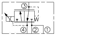
Without applied current, the TS98-T34 allows flow from 3 to 4 while blocking 2. When the coil is energized, 3 is connected to 2, and pressure at 3 is controlled proportional to the amount of current applied to the coil. If pressure at 3 exceeds the setting induced by the coil, pressure is relieved to 4.
Back pressure on port 4 becomes additive to the pressure setting at a 1:1 ratio.
Note: This product may be customized for special OEM performance characteristics. Consult factory.
• Economical drop-in style.
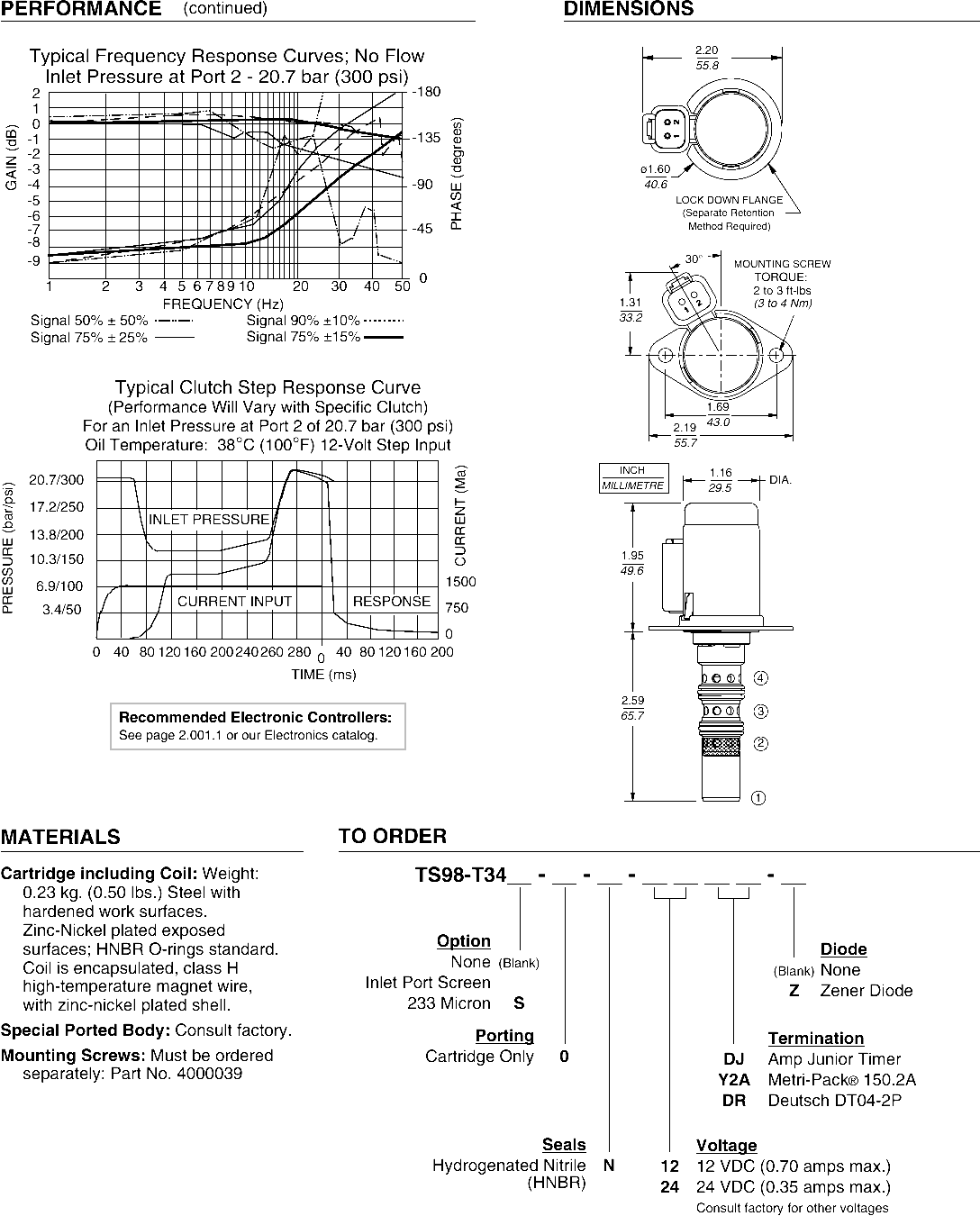
• 12 or 24 VDC coils.
• Several push-on termination options.
• Optional 233 micron mesh screen
• Integral waterproof coil standard.See page 3.400.1">3.400.1">3.400.1 for a description of tests conducted to verify coil waterproofing.
Maximum Inlet Pressure and Regulated Pressure: 30 bar (435 psi)
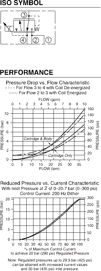
Maximum Control Current: To achieve 20 bar (290 psi) regulated pressure:0.85 amps for 12 VDC coil; 0.43 amps for 24 VDC coilNote: Regulated pressures up to 29.3 bar (425 psi) can be attained with increased current values and 30 bar (435 psi) inlet pressure.
Deadband: 0.150 amps @ 12 VDC; 0.075 amps @ 24 VDC
Hysteresis: 5% PWM for 20 bar (290 psi) control pressure
Reducing/Relieving Pressure Range from Zero to Maximum Control Current: 0–20.7 bar (0–300 psi)
Rated Flow: Port 3 to 4 with coil de-energized: 30 lpm (8 gpm)
Maximum Pilot Flow: 0.55 lpm (0.15 gpm) with 20.7 bar (300 psi) inlet
Flow Path: Free Flow: 3 to 4 coil de-energized; Reduced: 2 to 3 coil energized; Relieving: 3 to 4 coil energized; Port 1 is not plumbed externally
Oil Temperature: -40 to 120°C (-40 to 248°F)
Ambient Air Temperature: -40 to 120°C (-40 to 248°F)
Filtration: See page 9.010.1
Fluids: Mineral-based or synthetics with lubricating properties at viscosities of 7.4 to 420 cSt (50 to 2000 sus); See Temperature and Oil Viscosity, page 9.060.1
Installation Recommendation: When possible, the valve should be mounted below the reservoir oil level. This will maintain oil in the armature preventing trapped air instability. If this is not feasible, mount the valve horizontally for best results.
Flange Mounting Screws: M5 x 8; Part No. 4000039 (not provided with valve)
Cavity: VC-T003; See page 9.111.1;
Cavity Tool: CT-T003R0-x-G; See page 8.600.1
Seal Kit: SK98-T3N; See page 8.650.1
ISO SYMBOL
PERFORMANCEFLOW (gpm)FLOW (lpm)PRESSURE (bar)PRESSURE (psi)Pressure Drop vs. Flow Characteristic- - - - For Flow 3 to 4 with Coil De-energized—— For Flow 2 to 3 with Coil Energized12635478910201401204060801002468105102015302535160Cartridge & BodyCartridge OnlyPRESSURE (psi)50100150200250300PRESSURE (bar)5101520% of Maximum Control Currentto achieve 20 bar (290 psi) Regulated PressureNote: Regulated pressures up to 29.3 bar (425 psi)can be attained with increased current valuesand 30 bar (435 psi) inlet pressure.201030507090406080100Reduced Pressure vs. Current CharacteristicWith Inlet Pressure at 2 of 0–20.7 bar (0–300 psi)Control Current: 200 Hz Dither2134ORCE.com®