Item In Stock
A screw-in, cartridge-style, pilot-operated, spool-type reducing/relieving valve, which can be infi nitely adjusted across a prescribed range using a variable electric input. Pressure output is proportional to DC current input. This valve is intended for use as a pressure limiting device in demanding applications.
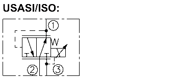
The TS12-36 allows flow from ➁ to ➀ until pressure at ➀ equals the setting determined by the coil current. Port ➂ is typically connected to the reservoir. If external load increases the pressure at ➀ beyond this setting, pressure is relieved by allowing flow from ➀ to ➂. Minimum pressure at ➀ without any current is 100 psi.If external circuitry allows the pressure at ➁ to fall below the pressure at ➀, the valve will allow free flow from ➀ to ➁ regardless of the setting of the valve or the amount of current in the coil.
• 12 and 24 volt coils, standard or optional waterproofed.
Maximum Operating Pressure: Ports ➀ and ➁: 276 bar (4000 psi)
Maximum Tank Pressure: Port ➂: 68.9 bar (1000 psi); Note: Tank pressure is additive to regulated pressure.
Reduced Pressure Range from Zero to Maximum Controlled Current:
A: 6.9–207 bar (100–3000 psi);
B: 6.9–172 bar (100–2500 psi)
C: 6.9–138 bar (100–2000 psi)
Maximum Pilot Flow and Leakage: 0.49 lpm (0.13 gpm) with max. control current and with inlet pressure at 276 bar (4000 psi) at regulated flow of 3.8 lpm (1 gpm).
Flow Path: Free Flow: ➀ to ➂ coil de-energized; Reducing: ➁ to ➀ coil energized; Relieving: ➀ to ➂ coil energized
Performance Life: Less than 5% change in the slope of the pressure vs current characteristics over one million cycles.
Hysteresis: Less than 3%.
Temperature: -40 to 120°C (-40 to 250°F) with Buna N seals.
Filtration: See page 9.010.1
Fluids: Mineral-based or synthetics with lubricating properties at viscosities of 7.4 to 420 cSt (50 to 2000 sus); See Temperature and Oil Viscosity, page 9.060.1
Installation Recommendation: When possible, the valve should be mounted below the reservoir oil level. This will maintain oil in the armature preventing trapped air instability. If this is not feasible, mount the valve horizontally for best results.
Cavity: VC12-3; See page 9.110.1;
Ca
vity Tool: CT12-3XX; See page 8.600.1
Seal Kit: SK12-3X-BM; See page 8.650.1
Coil Nut: Part No. 4526330; For E-coils manufactured prior to 1-1-04, see page 3.400.1">3.400.1">3.400.1 for coil nut info.