Item In Stock
A proportional solenoid-operated, two-way, spool-type, normally open, bi-directional, screw-in hydraulic cartridge valve.
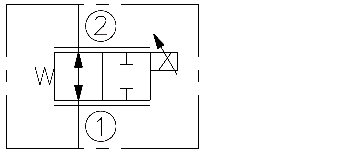
When de-energized, the SP10-25 allows flow from 2 to 1 or from 1 to 2. When partially energized, the valve begins to throttle the flow in either direction. When fully energized, flow is blocked in either direction.
External circuitry is required to ramp current.
Note: If low voltage is expected on the machine, 12 or 24 volt systems will require the use of 10 volt or 20 volt coils respectively. See “SP Valves and Coil Operating Parameters,” page 2.002.1.
• Industry-common cavity.
• Continuous-duty rated coils.
• Hardened precision spool and cage for long life.
• Optional waterproof E-Coils rated up to IP69K.
Operating Pressure: 207 bar (3000 psi)
Electrical Parameters:
Coil
Typical Max.
Current (amp) at 0 gpm
Typical Resistance
±5% at 20°C (ohms)
12 VDC
24 VDC
12 VDC
24 VDC
D-Coil1.20 amp 0.60 amp7.2 ±3%28.8 ±5%
E-Coil1.40 amp 0.70 amp7.09 ±3% 28.5 ±5%
Flow Rating: 18.9 lpm (5 gpm)
Max. Internal Leakage: 196 cc/minute (10 cu. in./minute) at 207 bar (3000 psi)
Operating Temperature: -40 to 100°C (-40° to 212°F) with standard Buna N seals
-26 to 204°C (-15°F to 400°F) with Viton seals
-54 to 107°C (-65°F to 225°F) with Polyurethane seals
Filtration: See page 9.010.1
Fluids: Mineral-based or synthetics with lubricating properties at viscosities of 7.4 to 420 cSt (50 to 2000 sus); See Temperature and Oil Viscosity, page 9.060.1
Installation: No Restrictions. See page 9.020.1
Cavity: VC10-2; See page 9.110.1;
Cavity Tool: CT10-2XX; See page 8.600.1
Seal Kit: SK10-2X-M; See page 8.650.1
Coil Nut: Part No. 7004400ELECTRO-PROPORTIONAL VALVES—
FLOW CONTROL
ISO SYMBOL
2.029.1
PERFORMANCEORCE.com®3.4/506.9/10010.3/15013.8/20017.2/25020.7/3007.623.8115.9411.4318.9522.76FLOW lpm/gpmPRESSURE bar/psiPressure Drop (No Coil Current)2 to 11 to 2Flow vs. Current 10.3 bar (150 psi) with Compensator EC10-32-0-N-150Flow 1–2 —; Flow 2–1 – – –3.8/1.07.6/2.011.4/3.018.9/5.015.9/4.00.1 0.20.40.30.50.8 0.9 1.0 1.1 1.20.6 0.7Amps:FLOW lpm/gpm3.8/1.07.6/2.011.4/3.018.9/5.015.1/4.0Flow vs. Current34.5 bar (500 psi): Flow 1–2 —; Flow 2–1 – – –207 bar (3000 psi): Flow 1–2 - - - -; Flow 2–1 — - —0.1 0.20.40.30.50.8 0.9 1.0 1.1 1.20.6 0.7Amps:FLOW lpm/gpm403020107080901005060% of Max. Control Current:403020107080901005060% of Max. Control Current:Increasing CurrentUpper CurvesDecreasing CurrentLower CurvesIncreasing CurrentUpper CurvesDecreasing CurrentLower Curves
Graphs based on 12 VDC "D" coil current.
NOTE: Curves shown are at constant pressure. Limiting flow to the valve or significant changes in dif-ferential pressure will change valve performance. Without a pressure compensator, the valve requires a minimum of 250 psid to achieve stable control of the spool as shown on the flow vs. current graphs.