Item In Stock
A direct-acting, spool-type, proportional, drop-in-style, flange-mounted, pressure reducing/relieving valve, which can be infinitely adjusted across a prescribed range using a variable electric input. Pressure output is proportional to DC current input. The E-coil is an integral part of the valve assembly, and cannot be replaced or field-serviced.
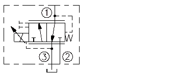
The EHPR98-T38B allows free flow from 1 to 3 when no current is applied to the coil. When the coil is energized, 2 is connected to 1. Increasing current applied to the coil will increase the control (reduced) pressure proportionally. If pressure at 1 exceeds the setting induced by the coil, pressure from 1 is relieved to 2.
Note: Operation of manual override option: Rotate manual override screw clockwise until desired regulated pressure is achieved.
• Economical drop-in style. • 1000-hour salt spray protection.
• Integral waterproof coil standard.
• Optional 142 micron screen at inlet.
Maximum Inlet Pressure: 241 bar (3500 psi) at Port 2; 57 bar (820 psi) at Port 1; 34 bar (500 psi) at Port 3.
Flow Rating: 18.9 lpm (5.0 gpm)
Maximum Internal Leakage: Energized: 393 ml/min. (24 cu. in./min.) at 241 bar (3500 psi); De-energized: 100 ml/min. (6 cu. in./min.) at 241 bar (3500 psi)
Cycle Life: One million cycles.
Oil Operating Fluid Temperature: -40° to 149°C (-40° to 300°F)
Storage Temperature: -40° to 70°C (-40° to 160°F)
Ambient Temperature: -40° to 80°C (-40° to 176°F)
Maximum Control Current: 1.38 amps for 10 VDC coil; 1.30 amps for 12 VDC coil;0.69 amps for 20 VDC coil; 0.65 amps for 24 VDC coil
Control Pressure at Maximum Control Current: 56.6 bar (820 psi)
Hysteresis: at 100 Hz PWM: 4% of maximum control pressure
Resistance: 4.3 ohm (10V); 5.2 ohm (12V); 17.5 ohm (20V); 20.9 ohm (24V)
Valve Inductance: 80 mH (12V)
Environmental Rating: IP69K
Filtration: See page 9.010.1
Fluids: Mineral-based or synthetics with lubricating properties at viscosities of 7.4 to 420 cSt (50 to 2000 sus); See Temperature and Oil Viscosity, page 9.060.1
Cavity: VC-T011; See page 9.111.1
Cavity Tool: CT-T011R0-x-G; See page 8.600.1
Seal Kits: SK-T011-N; SK-T011-V; See page 8.650.1
H
YDRA
F
ORCE.com®FLOW lpm/gpmPRESSURE bar/psiPressure Drop vs. FlowCartridge Only1 to 3 ———; 2 to 1 - - - - -3.4/506.9/10010.3/15013.8/20017.2/2503.81.07.62.011.43.015.14.018.95.0Relieving Pressure 1 to 3Typical Relieving/Reducing Pressure vs. Flow CharacteristicTypical Relieving Pressure at Various %s of Maximum Control CurrentInlet: 69 bar/1000 psi ——; Inlet 241 bar/3500 psi – – –(Curves overlap on Relieving Pressure side of graph); 150 Hz PWM (Both Directions)FLOW lpm/gpm15.14.015.14.018.95.018.95.011.43.011.43.07.62.07.62.03.81.03.81.0Reducing Pressure 2 to 130% Max. Control Current0% Max. Control Current% of MAXIMUM RELIEF PRESSURE% of MAXIMUM REDUCING PRESSURE50257510012515050257510012515045% Max. Control Current17560% Max. Control Current75% Max. Control Current100% Max. Control CurrentCURRENT ampsPRESSURE bar/psiReducing Pressure vs. Current6.9/10013.8/20020.7/30027.6/40062.1/9000.2 0.4 0.61.00.81.41.2Reducing Pressure 2 to 1Inlet: 34.5 bar/500 psi; 150 Hz PWM; 12V Coil34.5/50041.4/60048.3/70055.2/800