Item In Stock
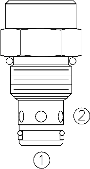
A screw-in, cartridge-style, hydraulic check valve for use as a blocking or load-holding device. The cartridge incorporates a low flow thermal relief valve intended to prevent cylinder damage resulting from temperature-induced pressure intensifi cation.
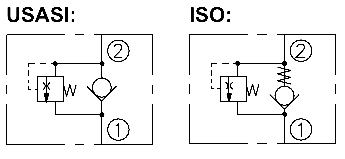
The CV10-28 allows flow from ➀ to ➁, while blocking oil flow in the opposite direction. If the pressure at ➁ exceeds the thermal relief valve setting, a small amount of oil will be allowed to pass from ➁ to ➀, preventing cylinder damage from pressure intensifi cation.
NOTE: The relief valve feature is not intended for use in dynamic pressure limiting
applications. Consult factory.
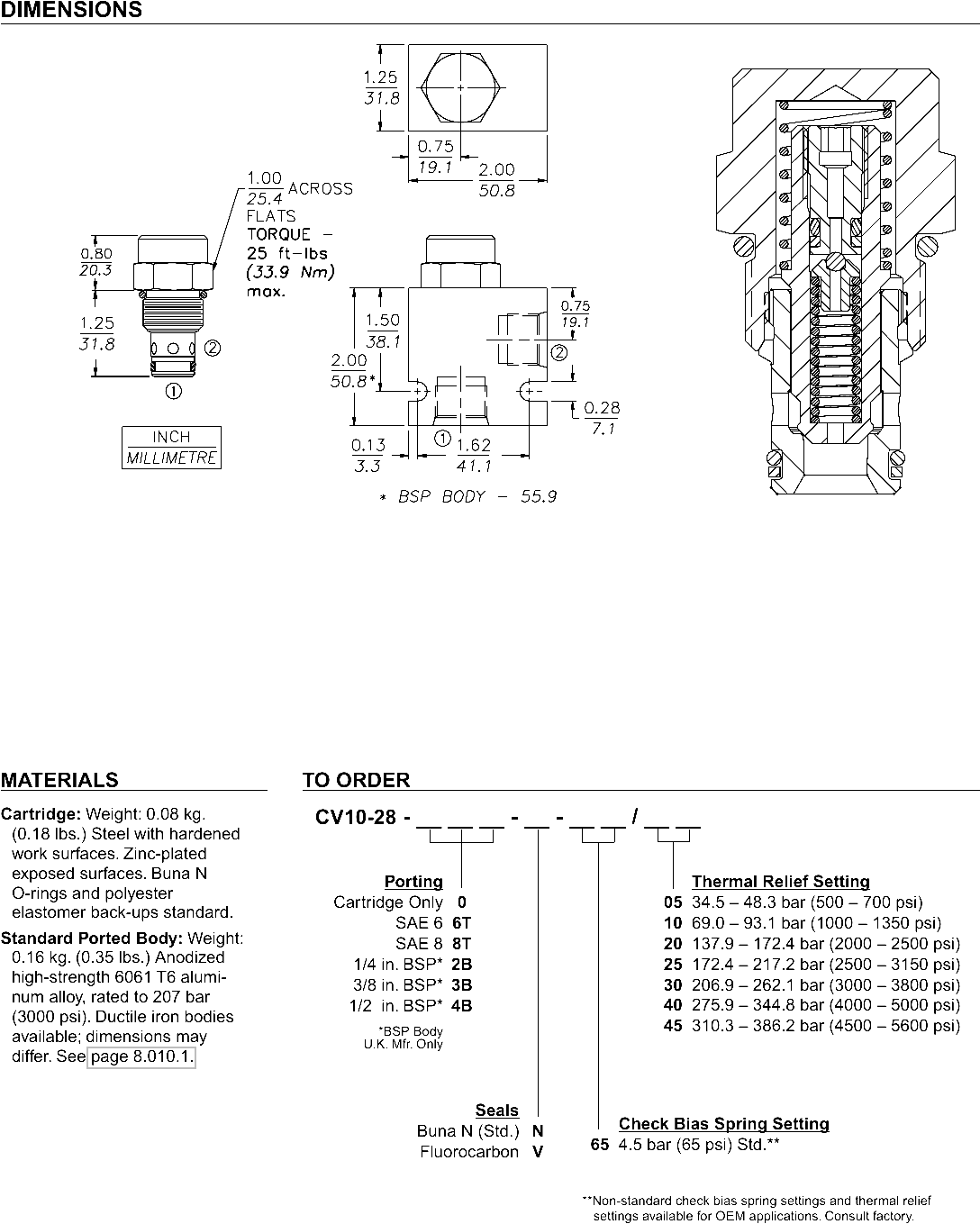
• Hardened seats for long life and low leakage.• Industry common cavity.
Formula for Thermal Expansion: ΔP = 57.7 x ΔT (where ΔP is in psi; ΔT is in °F)
Operating Pressure: 241 bar (3500 psi)
Proof Pressure: 390 bar (5700 psi)
Thermal Relief Settings:
05 34.5 – 48.3 bar (500 – 700 psi)
10 69.0 – 93.1 bar (1000 – 1350 psi)
20 137.9 – 172.4 bar (2000 – 2500 psi)
25 172.4 – 217.2 bar (2500 – 3150 psi)
30 206.9 – 262.1 bar (3000 – 3800 psi)
40 275.9 – 344.8 bar (4000 – 5000 psi)
45 310.3 – 386.2 bar (4500 – 5600 psi)
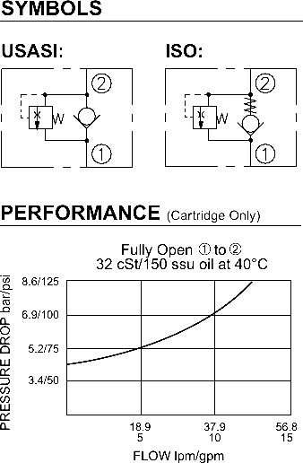
Flow: See Performance Chart
Internal Leakage: 0.25 cc/minute (5 drops/minute) max. at 240 bar (3500 psi)
Standard Check Bias Spring at Crack: 4.5 bar (65 psi)
Check ➀
to ➁
Crack Pressure Defi ned: Gauge bar (psi) evident at ➀ at 16.4 cc/minute (1 cu. in./minute) attained at ➁
Temperature: -40 to 120°C
Filtration: See page 9.010.1
Fluids: Mineral-based or synthetics with lubricating properties at viscosities of 7.4 to 420 cSt (50 to 2000 sus); See Temperature and Oil Viscosity, page 9.060.1
Installation: No restrictions; See page 9.020.1
Cavity: VC10-2; See page 9.110.1
Cavity Tool: CT10-2XX; See page 8.600.1
Seal Kit: SK10-2X-T; See page 8.650.1