Item In Stock
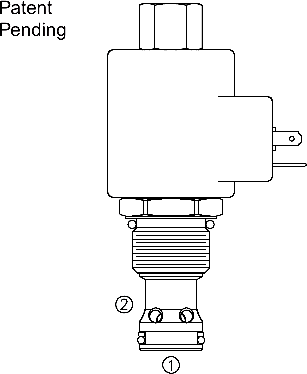
A screw-in, cartridge-style, pilot-operated, spool-type hydraulic relief valve, which can be infi nitely adjusted across a prescribed range using a variable electric input. Pressure output is proportional to DC current input. This valve is intended for use as a pressure limiting device in demanding applications.
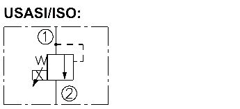
The TS12-26 blocks flow from ➀ to ➁ until suffi cient pressure is present at ➀ to open the pilot section by offsetting the electrically induced solenoid force. With no current
applied to the solenoid, the valve will relieve at approximately 100 psi.
The optional manual override allows the valve to be set when the electric supply is
lost. The manual setting is added to the electric setting. To prevent the system from
being over pressurized, the manual override should always be disengaged prior to
applying power to the coil.
• Manual Override option.
• Industry common cavity.
• 12 and 24 volt coils standard.
• Optional waterproof E-Coils rated up to IP69K.
Maximum Operating Pressure: 241 bar (3500 psi)
Maximum Control Current: 1.10 amps for 12 VDC coil; 0.55 amps for 24 VDC coil
Relief Pressure Range from Zero to Maximum Control Current:
A: 6.9–207 bar (100–3000 psi)
B: 6.9–138 bar (100–2000 psi)
C: 2.1–69 bar (30–1000 psi)
Rated Flow: 189 lpm (50 gpm); See Performance Charts
Maximum Pilot Flow:
A: 1.9 lpm (.5 gpm);
B: 1.3 lpm (.35 gpm);
C: .9 lpm (.25 gpm)
Hysteresis: Less than 3%
Flow Path: Free Flow: ➀ to ➁ coil de-energized; Relieving: ➀ to ➁ coil energized
Temperature: -40 to 100°C (-40 to 212°F) with standard Buna N seals
Filtration: See page 9.010.1
Fluids: Mineral-based or synthetics with lubricating properties at viscosities of 7.4 to 420 cSt (50 to 2000 sus); See Temperature and Oil Viscosity, page 9.060.1
Installation Recommendation: When possible, the valve should be mounted below the reservoir oil level. This will maintain oil in the armature preventing trapped air instability. If this is not feasible, mount the valve horizontally for best results.
Cavity: VC12-2; See page 9.112.1;
Cavity Tool: CT12-2XX; See page 8.600.1
Seal Kit: SK12-2X-B; See page 8.650.1
Coil Nut: Part No. 4540560; For E-coils manufactured prior to 1-1-04, see page 3.400.1">3.400.1">3.400.1 for coil nut info.